

Article on Concentricity in deep hole applications
Recent News - February 20, 2014Deep Hole Geometry as Machined – Part Four
by Geoff Ginader
President American Hollow Boring
How straight will the hole be? This is a critical question to answer in most deep hole drilling boring and machining applications. The question cuts across the critical connections between design, project management, and manufacturing. Part 3 of this series explored Deep Hole Geometry as Specified with emphasis on the balance of cost effectiveness vs. feature control considering the range of form attributes. In this article, we will continue the focus on the bore considering the range of variation and precision available as machined.
Given the exact specification of rough or finish bored holes as conveyed by drawings and other controlling documents such as purchase orders, a manufacturing plan can be developed. Machine shop operations available for generating or improving deep bore straightness in order of accuracy include:
- Straightness from drilling and trepanning
- Straightness from mechanical straightening in a press
- Straightness from finish boring and pull boring
- Straightness and roundness from deep boring in a lathe
- Roundness and uniform finish from honing
- Concentricity from other machining in a lathe or milling machine
Along with a machining plan, an inspection plan enables and verifies the meeting of all requirements.
In addition to micrometers, calipers, roughness testers, indicators, and scales; deep bores may require special equipment such as bore gages, borescopes, ultrasonic equipment and other special gages to verify size, finish, location, and runout over the complete inside and outside of the part.
An important goal of manufacturing is to produce parts without variation. In reality, as with most machining operations, deep hole bores can have variations within tolerance or beyond tolerance. It is important to understand possible variations and plan to allow or prevent them as required. Variations can be measured and described as follows:
|
Feature Imperfections and Defects Bow Taper Scoremarks Rings Oversize, undersize Chatter Out of roundness Runout, drift Mismatch, skew |
Ideal Properties Straightness Straightness and uniform size Uniform size and finish Uniform size and finish Uniform size, in tolerance Uniform surface finish Roundness Running true, concentricity and roundness Concentricity, running true |
In rough bored holes with wide tolerances and no finish requirement, bores may be produced in a single operation with little concern for rings, chatter, score marks or other imperfections. As we have seen in part 3, stock may be required to allow for significant runout.
In finish bored holes, better straightness, roundness, concentricity and tight tolerances can be generated. Recognize that as demands of tolerances, lengths, and complex geometry increase, so does cost of machining and verifying the range of finished attributes.
 In many cases, a balance can be struck with strategies to simply drill or trepan, hone, and machine true. For example, consider a workpiece that is Solid H13 tool steel 14” diameter by 80” long or 2m long. The desired part is with a through hole finishing at 5.118” or 130mm and OD of 13.78” or 350mm. Tolerances are +/-.005”, and the desired runout is .040” max or 1mm. This part can be drilled at a size just under tolerance, honed for final size, and the OD can be turned true to the bore to reduce runout from the drilling operation. In this example the drill removes the stock with adequate straightness, perhaps as much as .060” wall variation at the exit. The hone improves finish and roundness while achieving a uniform finish size. The turning operation reduces bore runout in the worst areas. Runout is independently verified with an indicator throughout the bore. It is very unlikely that runout will exceed .010” in any spot, but it could be as much as .040”.
Given tighter tolerances, such as runout requirement of .003” or better for the same H13 part, a new process must be used. One method is to drill an initial through hole and then bore in a lathe 40” from each end. OD turning may occur before boring to achieve more even cuts. The bore may then be finished in a hone to blend the center and achieve a better finish if needed. Runout is again verified and should come in under .003” over the entire length of the bore. Total indicator runout is less than the tolerance in this case which allows the straight bore to be located higher in the size tolerance if a blemish such as a ring or chatter develops at the low end of the tolerance. Bore size is measured all thorough the part with a boregage at different clock positions verifying size tolerance and measuring the roundness of the bore. Still other deep boring processes must be used if length here is double or triple to 240” and beyond.
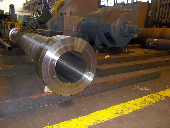
Image caption: 316 stainless steel cylinder 144” long with a bore size of 8.5” and with a main section wall thickness of 1.5”. The part was finish bored, honed, and machined at American Hollow Boring Co. with total indicator runout under .010” in the bore. With the bore complete, all other finished features were made to the drawing.
We have seen that many methods and tools are available to achieve and verify the significant requirements of deep bores as machined. With clear communication, confidence, and trust, great results are achievable. This is collaboration of engineering, project management, and manufacturing at its best. Be sure to contact the experts at American Hollow Boring Co. to review your specific project.
For further reading, we recommend you read all four parts of this series of articles on the topic of Concentricity in Deep Hole Applications. Also refer to “Dimensioning and Tolerancing: ASME Y14.5M-1994 (Engineering Drawing and Related Documentation Practices)” by the American Society of Mechanical Engineers (ASME), 1995, ISBN-10: 0791822230.